|
Output Relays
The devices that are used to
initiate a stop signal. The output relays (FSD1, FSD2 and SSD) use positively
guided contacts.
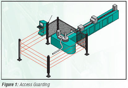
Perimeter Guarding
See Access Guarding.
Point of Operation
The area of the guarded machine
where a workpiece is positioned and a machine function (i.e.,shearing, forming,
punching, assembling, welding, etc.) is performed upon it.
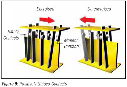
Positively Guided Contacts
Relay contacts that are mechanically
linked together, so that when the relay coil is energised or de-energised, all
of the linked contacts move together. If one set of contacts in the relay
becomes immobilised, no other contact of the same relay is able to move. The
function of positively guided contacts is to enable the safety circuit to check
the status of the relay. Positively guided contacts are also known as captive
contacts, locked contacts, forced-guided contacts or safety relays. See Figure 5
above.
Presence-Sensing-Device
Initiation (PSDI)
An application in which a
presence-sensing device is used to actually start the cycle of a machine. In a
typical situation, an operator manually positions a part in the machine for the
operation. When the operator moves out of the danger area, the presence-sensing
device starts the machine (without using a start switch). The machine cycle runs
to completion and the operator can then insert a new part and start another
cycle. The presence-sensing device continually guards the machine. Single break
mode is used when the part is automatically ejected after the machine operation.
Double break mode is used when the part is both inserted (to begin the
operation) and removed (after the operation) by the operator.
Receiver
The light-receiving component,
consisting of a row of synchronised photo transistors. The receiver, together
with the emitter (placed opposite), creates a light curtain called the detection
zone.
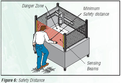
Safety Distance
For a normal approach, reference
ISO/DIS 13855 (EN 999) gives the following formula:
S = K x T + C where
S = The minimum safety distance in mm, from the
danger zone to the centre line of the detection zone. Minimum allowable safety
distance is 100 mm (175 mm for non-industrial applications) regardless of the
calculated value.
K = The standard maximum hand speed in mm/s according
to reference
ISO/DIN 13855 (EN 999). K = 2000 mm/s for values of S between 100 mm and 500
mm. If S > 500 mm, then K may be reduced to 1600 mm/s but S must remain > 500
mm.
T = The overall response time of the machine, the
time between the physical initiation of the safety device and the machine coming
to a stop or the risk being removed. This can be broken down into two parts: Ts
and Tr where
T = Ts + Tr
Ts = The response time of the machine measured between
the application of the stop signal and the machine coming to a stop or the risk
being removed. Ts is usually measured by a stoptime measuring device.
Tr = The response time of the safety device.
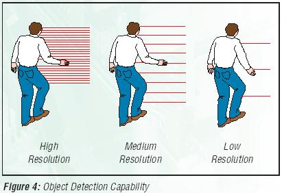
C = The additional distance in mm, based on the
intrusion of the hand or object towards the danger zone prior to actuation of
the safety device. If the Object Detection Capability is not greater than 40 mm:
C = 8 (d - 14). Always consult the manual for complete details on safety
distance calculation! See Figure 6.
|