|
Dimensional
Drawing
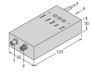
1 = Sensor Connector
2 = 24Vdc and PLC Connector
3 =Serial PC Interface
4 = 24Vdc supply via plug-in PSU |
● Interface between sensor and a PC
● Display of sensor functions
● Verification and change of
parameters via PC
● Switch point adjustments via push
buttons
● Interconnection of programming
device between sensor and PLC
● Saving of parameter settings on
disk or parameter print-outScope of
delivery
– RU-PDI programming device/interface
with connection cable to PC
– extension for connection of an
ultrasonic sensor
– 24 V plug-in power supply unit
– disk with programming software for
Windows and DOS |
Parameter programming
– lower and upper limit of switching range
– switching hysteresis
– blind zone
– upper limit of detection range
– beginning and end of analogue curve
– falling or rising analogue curve
– normally open or normally closed
switching function
– average forming
– multiplex function
– diffuse mode or opposed mode
– switching frequency
Technical data
Rated operational voltage
– 24 VDC or with plug-in power
supply unit
Hardware requirements
– PC or laptop with serial interface
COM1 oder COM2
|
Software requirements
– MS-Windows 3.x, Windows 95,
Windows NT
Function buttons
COPY function to copy parameters
from one sensor to another
BEGIN Teach-in: lower limit of switching
range/ of analogue range
END Teach-in: upper limit of switching
range/of analogue range
LED indications
LED green (POWER) device is energised
LED red (PROG) status LED for function buttons.
Flashing LED signals errors.
|